Digital Photomicrography for Gemologists
ABSTRACT
Until recently, film was the preferred medium used for capturing images through the microscope, primarily due to resolution limitations of digital-format cameras. The image quality that can now be achieved by digital cameras is equal, and in many ways superior, to the quality offered by film. Digital photomicrography allows gemologists the opportunity to instantly see the resultant images, which can then be adjusted with image-refining software so that they represent their subject as realistically as possible. This article offers examples of some basic techniques and tips on the application of digital processing to get the most out of photomicrographs.
INTRODUCTION
The inclusion scenes observed in the micro-world of gems often reveal a tremendous amount about the identity and origin of an unknown gemstone. By capturing these microcosms in a recorded image, the information is preserved for easy reference. This information can sometimes be limited due to the photomicrographer’s own knowledge of the subject, but resources such as the three-volume Photoatlas of Inclusions in Gemstones (Gübelin and Koivula 1986, 2005, 2008) aid in understanding the subjects the gemologist may encounter through the microscope.
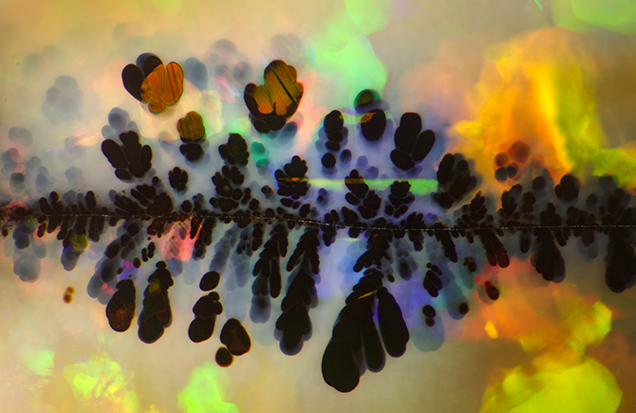
Photomicrography is the method by which images, magnified through a microscope, are collected by a camera. These images often represent subjects ranging in size from less than 1 mm to 1–2 cm. Photomicrographs do not only serve as educational and research references; many are aesthetically pleasing and can be viewed as examples of natural art, and have even been used as a marketing tool for gem materials (Koivula et al., 1994). All one has to do is attach a camera in the optical path of a microscope to take advantage of the beautiful micro-world of gems. This was previously accomplished using film, often with tremendous results due to the superb color rendition and high resolution that film could offer. The downside to this method is the expense of developing and the delay in seeing the resultant image. As predicted by Koivula (2003), the limitations of film have essentially been eliminated by the digital age. Digital camera technology has developed to the point that image quality rivals that of film, and the photomicrographer no longer incurs the cost of developing film just to see the resultant image. Digital photography also allows for instantly viewing captured images and in making post-processing adjustments that gives the photographer the ability to compensate for sub-par lighting conditions and make post-capture corrections. This article covers the basics of gemological photomicrography, from equipment configurations to lighting conditions and image processing software, which will assist aspiring photomicrographers in merging science and art (figure 1).
THE MICROSCOPE
The most practical photomicrography system begins with a trinocular microscope to allow traditional observation and image capture simultaneously. However, a binocular microscope with a live display to a video monitor may also provide sufficient results, even if it is not as easy to use. There are many limiting factors in photomicrography, one of which is the quality of the optics between the subject and the camera. For the best results, photomicrographers should acquire the best optics possible within their budget. It is usually better to purchase a used high-quality microscope with excellent optics than a new microscope with merely adequate optics. As Internet commerce has evolved, it has become quite easy to purchase a high-quality used microscope for a reasonable price; however, this cost will still be in the range of a few thousand dollars for a good used microscope in working order. New microscopes with high-quality optics will cost several times that. Two recommended models no longer in production, but often available from online resellers, are the Wild Heerbrugg M400 series photomacroscopes and the Nikon SMZ10 trinocular head microscope (figure 2). Both instruments have excellent optics but offer their own unique features. The Nikon SMZ10 has the ability to capture stereo pairs for three-dimensional (3D) viewing by moving a selector switch that changes the optical path projected to the trinocular port. The Wild M400 has a single optical path that is perpendicular to the stage. This eliminates the lateral shift problems encountered as one adjusts the microscope stage in systems with angled optical paths. The downside to both of these microscopes is their age. Even though they are built to last several lifetimes, their scarcity can make it difficult to source desirable accessories such camera adapters, 2× objectives, and model-specific polarizing filters.
| Box A: The Evolution of the Gemological Microscope |
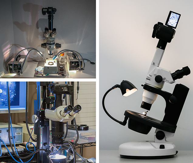
Gemological microscopy has evolved from the late 19th century drawtube brass microscopes (figure 3, top left) into using much more advanced stereomicroscopes that primarily used darkfield illumination. The application of this lighting to gemology was first patented by Robert Shipley Jr. in 1939 (figure 3, top right) (U.S. Patent no. 2,157,437); darkfield has essentially been the standard lighting environment for gemology ever since. Though there have been some advancement in optical trains and ergonomics, the gemological microscope has remained largely unchanged for several decades. In 2011, GIA’s Carlsbad laboratory acquired a custom-outfitted compound microscope for research applications. This Nikon Eclipse LV100 (figure 3, bottom left) can provide a viewing magnification of up to 1000×, whereas standard gemological microscopes usually have a maximum viewing magnification of approximately 120× with the use of an auxiliary doubling lens. This microscope system is outfitted with extra-long working distance objectives, differential interference contrast components, an assortment of filters, fluorescence imaging capabilities, and Nikon’s NIS-Elements software, which can control the stage height for automated extended depth-of-field imaging. This microscope will allow researchers to reexamine specimens with a new perspective and could enable the observation of previously unseen features in gem materials. While not necessarily a practical microscope for routine gemological examination, this type of system could represent the future in gemological discovery. In April 2015, the inclusion research department at the Carlsbad lab acquired a well-equipped Nikon SMZ25 microscope system with a 25:1 zoom ratio, a Nikon DS-Ri2 high-resolution digital camera and Super High Resolution (SHR) objectives (figure 3, bottom right). This microscope system demonstrates the latest developments in optical microscopy and digital photomicrography.
Figure 3. Top left: This late 19th century brass monocular microscope was outfitted for studying gemstones, and its base is stamped “The Gemmoscope.” Top right: This Bausch and Lomb microscope uses the Shipley patented darkfield lighting environment, which has become the standard in gemology. Bottom left: The author examines the surface of a diamond crystal using the GIA Carlsbad laboratory’s Nikon Eclipse LV100 compound microscope. Bottom right: GIA’s analytical microscopist, John Koivula, with a recently acquired Nikon SMZ25 microscope. Photos by Nathan Renfro (top) and Kevin Schumacher (bottom).
|
DIGITAL CAMERAS
Since the inception of the digital camera concept in 1972 (Trenholm, 2007), it has been a long road to develop the technology that would surpass the quality of film. This development in digital imaging has essentially been the death of film photography; the only practical option for photomicrographers today is to adapt their microscope to a digital camera. One of the most significant benefits of the digital age is that photography has become much more cost effective, allowing many more people to enjoy this rewarding hobby. Previously, the cost of purchasing and developing high-quality film could be as much as $2–$3 per final bracketed image (J. Koivula, pers. comm., 2014). Now, the photomicrographer can capture as many images as desired at no additional expense. This facilitates repeated practice, as one does not have to be concerned with the cost of film “waste.”
Modern digital cameras with complementary metal oxide semiconductor (CMOS) sensors offer excellent color rendition, very high resolution capability, and a tremendous amount of control over many parameters, including shutter speed, white balance, International Organization for Standardization (ISO) settings, and exposure compensation. While budget is important when choosing a camera for photomicrography, other factors to consider are resolution, weight, vibration control, and remote control capability. Camera choices can be as simple as the digital camera on your smartphone (Boehm, 2014) all the way to a professional-grade digital single-lens reflex (DSLR) camera. The author currently uses a Canon 6D DSLR. Several notable features are the high-resolution, full-frame (36 mm × 24 mm) sensor and Wi-Fi capability for wireless remote shooting, which helps to eliminate potential image-blurring vibrations. This particular camera is also appealing because of the lightweight composite body, compared to other DSLR full-frame cameras with heavier alloy bodies, helps to prevent the focusing rack from becoming overloaded, making it easier to maintain image focus. Many of these features can be found on other DSLR cameras as well; this model serves as an example of criteria to consider when selecting a camera for photomicrography.
ADAPTING A DIGITAL CAMERA TO A MICROSCOPE
One of the biggest challenges in adapting almost any microscope for image capture is mating the camera to the microscope so that it is parfocal. This is when the image at the camera sensor is in focus at the same time as the image viewed in the microscope oculars. Parfocality makes image composition much easier and saves significant time. Certain manufacturers of specialty adapters offer ready-made solutions for camera adaptation, but some microscopes may require additional components to achieve parfocality. The author’s Nikon SMZ10 was mated to a DSLR camera by using a Diagnostic Instruments PA1-12A adapter tube with a helicoid-style extension tube for parfocality adjustment; this was then connected to a Canon adapter for the camera (figure 4).

Once the camera is selected and attached to the microscope, there are additional considerations regarding the relay lens in the trinocular port. The primary factor that should influence your choice of magnification of this optical element is the sensor size of your camera. The best choice of relay optic is one that completely fills the sensor (to avoid vignetting, or fuzzy dark edges) and does not waste too much light through over-magnification as the image is projected on the camera sensor.
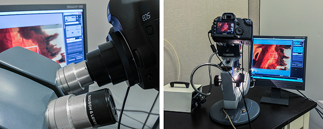
For microscopes without a trinocular port, adapters that mount the camera onto an ocular present a very reasonable solution (figure 5, left). Since traditional observation is not possible in this configuration, the photomicrographer must rely on a live view displayed on a monitor to set up the specimen (figure 5, right). With the significant advances in smartphone cameras, it is possible for the hobbyist to take decent-quality photomicrographs with these devices (Boehm, 2014). Inexpensive products to facilitate smartphone photomicrography also exist (Overton, 2010). The most obvious advantage to smartphone photomicrography is portability, a simple matter of carrying a smartphone and a loupe in the field (Boehm, 2014).
GETTING STARTED: CLEANING AND VIBRATION CONTROL
Two important considerations for photography through the microscope in achieving satisfactory results are sample cleaning and vibration control (Koivula, 1981). A clean sample simply makes a much more striking image. If one is investing the time required to take a high-quality photomicrograph, the results are dramatically improved if some time is spent properly cleaning a sample prior to setting up the image. Typically, this can be accomplished with a stone cloth and a damp sponge to remove as much dust and finger oil as possible. This will save significant time in post-capture image processing and dust spot removal, which will be discussed later in the article.
Vibrations can cause loss of detail by blurring an image. This happens when subject movement occurs over the exposure time. Two solutions for this problem are eliminating causes of movement or decreasing exposure time. By making the microscope more rigid or isolated from the environment, the photomicrographer minimizes vibration-induced problems. A floating optical table is best, but this is generally too expensive for hobbyists. To help eliminate vibrational movement, one can add shock-absorbing anti-vibration mounts or rubber pads underneath the microscope to help prevent vibrations from reaching the subject.
Another solution to help eliminate vibration-induced blurring is to decrease the exposure time so there is less chance for the subject to move. With digital photomicrography, you can increase the light sensitivity of your camera by adjusting the ISO setting, the modern equivalent to the American Standards Association’s (ASA) “film speed.” If your camera is more sensitive to light, then the required exposure time decreases; however, if the ISO is adjusted too high, image quality may suffer from what is known as “noise” or a grainy salt-and-pepper type appearance.
For users of DSLR cameras in particular, the mirror and shutter movements may cause some additional vibrations. If selecting a DSLR digital camera for photomicrography, it may be worthwhile to choose one with a “silent shutter” mode, which will greatly reduce camera-induced vibrations.
LIGHTING TECHNIQUES
Lighting is the single most important factor in taking a high-quality photomicrograph. Without proper illumination, satisfactory results will never be achieved. Most gemologists are familiar with several types of broadly suitable lighting. Brightfield, darkfield, and reflected light are the types of illumination typically used in gemology. There are several other types of environments or modifications to these types of light that will greatly enhance the appearance of almost any photomicrograph. The difficulty is in knowing which type of lighting or combination of lighting to use for a given inclusion scene. This valuable insight, which must be learned through reading literature on photomicrography and significant practice, has been extensively covered (Koivula 1981, 1982a, 1982b, 1984, 2003).
Darkfield illumination is probably the most familiar type of lighting for general observation, because most gemological microscopes are equipped with a darkfield base. This type of lighting allows light-scattering inclusions to stand out in high relief against a dark background and can be useful for highlighting small inclusions (figure 6, left). While this lighting environment is useful for general observation, the high degree of contrast produced between the inclusions and background is not always desirable or aesthetically pleasing. One important consideration in darkfield photomicrography is that undesirable dust particles and surface scratches will be conspicuous, which may limit this lighting environment in all but the most pristine of specimens.
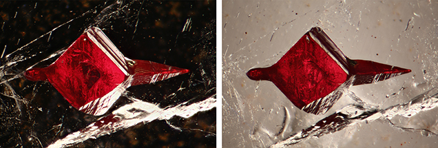
Brightfield illumination, or transmitted light, is a technique in which the specimen is placed between the objective and a bright direct illumination source (figure 6, right). This type of lighting is particularly useful for examining color-zoned specimens and masking the appearance of fine dust particles; however, detail may be lost when examining overly dark or opaque inclusions. Brightfield illumination can be further enhanced by using a diffuser plate to control the light intensity if direct transmitted light sacrifices too much detail by creating bright reflective areas, sometimes called “hot spots” (Koivula, 2003).
Diffuse reflected light is useful for examining surface features and revealing differences in luster between two dissimilar materials. This lighting is also suitable for detecting coatings, as they often display a higher luster than the substrate material.
Fiber-optic illumination may be the most underused and single most useful form of illumination in gemology. Quite often, crystallographically-oriented inclusions can be well hidden unless an illumination direction can be achieved to facilitate light scatter from these particles. Because of the widely adjustable position of the fiber-optic illuminator, hidden inclusions are often easily revealed (figure 7). When using a fiber-optic illuminator, controlled light can be guided to the subject at an oblique angle to highlight any unseen iridescent components (figure 8; Koivula, 1982a). Crystallographically-oriented thin film inclusions are often particularly responsive to oblique fiber-optic illumination (Koivula, 1980), revealing vivid colors when this method is used (figure 9).

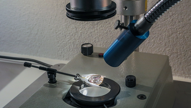

While the use of polarized light is quite familiar to most gemologists by way of the polariscope, using polarized light in conjunction with the microscope may be foreign. The most significant use of a polarizer in gemological photomicrography is the elimination of doubling in birefringent materials by placing a polarizing filter, called an analyzer, between the objective and the subject (figure 10). This polarizing filter will eliminate one of the refraction directions, thereby making the image appear singly refractive. Crossed-polarized light, created by adding another polarizing filter between the subject and light source oriented 90 degrees to the plane of polarization of the analyzer, can also reveal low-relief, nearly invisible inclusions in high contrast due to strain and optical misalignment. Also, the vibrant colors occasionally observed from birefringent inclusions in polarized light are a welcome sight to almost any photomicrographer (figure 11). Polarized light can be further enhanced by the use of a first-order red compensator. Also known as a full-wave plate, this type of filter significantly decreases the exposure time required to capture an image in polarized light and can dramatically enhance strain color (figure 12) (Koivula, 1984).
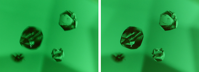


Ultraviolet (UV) light has limited but occasional use in photomicrography. UV illumination can induce a fluorescent reaction in certain subjects, producing visually striking results that can be photographed (figure 13); however, exposure times greatly increase, as the lumination intensity is typically far less than any other lighting environment mentioned. This increased exposure time may lead to vibration-induced blurring of images. Also, it should be noted that UV light may be harmful to the photomicrographer’s eyes, so exposure should be kept to a minimum and proper protective equipment should always be used.

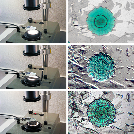
The photomicrographer will quickly realize that sometimes no single type of lighting is adequate to produce a high-quality photomicrograph for a particular specimen. Significantly more impressive results may be produced using combinations and/or modifications of the lighting previously mentioned. Learning which combinations to use and when to use them is an important skill developed with practice. Once the correct illumination sources are selected, the next challenge is controlling the light in order to balance the contrast in an image and resolve the most detail. One of the biggest problems in lighting is controlling hot spots. A useful technique utilizes a piece of opaque black paper (or similar material) carefully inserted to block the precise source of light causing the hot spot without blocking the desirable light that is illuminating the subject (Koivula, 2003). Another lighting modification is a similar, carefully controlled approach of contrast enhancement called “shadowing” (Koivula, 1982b). Shadowing effects provide a tremendous amount of contrast in inherently low-contrast specimens by adding dark areas to otherwise light subjects (figure 14). To create shadowed illumination, an opaque black paper or similar material is slowly moved in between the illumination source and the specimen until contrast and detail are at a maximum (see again figure 14). This shadowing technique can be applied to darkfield, brightfield, and even reflected light environments.
DIFFERENTIAL INTERFERENCE CONTRAST
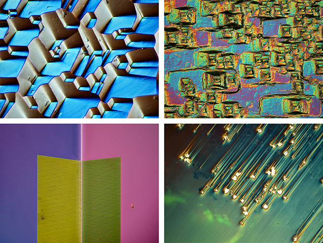
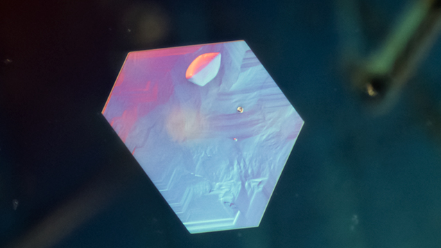
A remarkable lighting technique that has only occasionally been applied to gemology is episcopic differential interference contrast (DIC). This reflected light, contrast-enhancing technique (Koivula, 2000) has produced some of the most vibrant displays of color and geometric patterns ever observed in gemology. A specialized microscope equipped with a Nomarski-modified Wollaston prism and polarizing filters is required for this type of microscopy (figure 15). Sheared wave fronts created by the prism are focused on the specimen by the objective and travel slightly different path lengths due to the surface topography of the specimen. These variations in topography are transformed into amplitude or intensity variations, revealing the topographic profile of the specimen (Brandmaier et al., 2013). DIC microscopy is capable of yielding both grayscale images and “optically stained” full-color images by simply adjusting the position of the prism in the optical path (figure 15). The surfaces of highly-reflective mineral inclusions can also be carefully examined through their host mineral using DIC (figure 16); however, this technique is not always possible for subsurface inclusions if they are located too deep in the host material, or if the host is too reflective.
DIGITAL IMAGE PROCESSING
In addition to the previously mentioned advantages, digital photography also allows for a wide range of post-processing tools that can improve image appearance. While software makes it possible to modify images to the point that the image does not accurately represent the subject, the goal of gemological photomicrography is to document inclusions as realistically as possible. Therefore, it is not useful to digitally modify images beyond their natural observed appearance. Software enhancement that makes images appear as close to the actual subject as possible is a tremendously useful tool that, when applied appropriately, is very welcome in the digital photography world. Two particularly important image-processing tools are extended depth-of-field, also called “extended depth of focus” or “focus stacking” and high dynamic range (HDR) imaging.
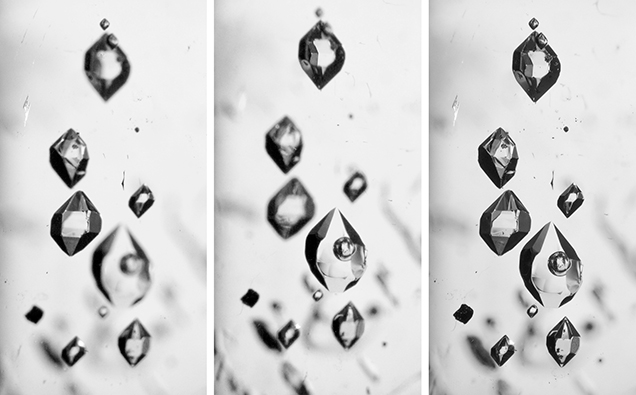
In an extended depth-of-field, is when a series of images are captured at regularly spaced focal planes and digitally combined to extend the depth-of-field beyond what is possible in a single image (figures 17 and 18). This is particularly important for photomicrography at high magnification, since depth-of-field decreases at higher magnification. This digital processing technique allows the photomicrographer to capture inclusion scenes with tremendous detail at high magnification that would otherwise be impossible in a single frame image. There are several programs to facilitate focus stacking, including Zerene Stacker (Prince, 2014), Helicon Focus, and NIS Elements. One requirement is that the image set must be stepped at fairly regular intervals. While it is possible to slowly turn the focus knob on a microscope by hand, it is impractical to do so in regular increments without some way to measure each step.

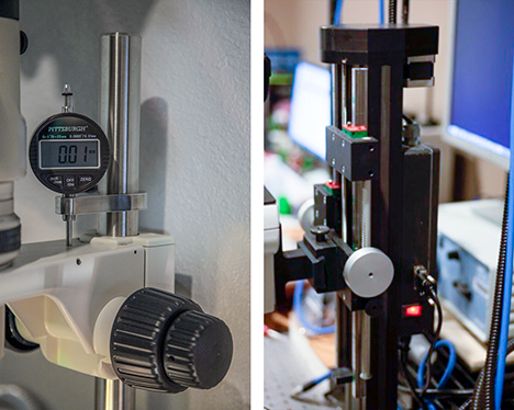
The addition of a dial indicator or similar measurement device on the microscope focusing rack may be a cost-effective solution, allowing regular focus intervals to facilitate extended depth-of-field imaging (figure 19, left). A focus mount with a fine adjustment will also help the user precisely index the focus height. More sophisticated solutions may involve a focus rail with a stepper motor, which can be digitally controlled through a compatible software program to index the microscope focus at very precise, regular intervals (figure 19, right). This equipment is particularly useful for very large depth ranges, which would require many images.
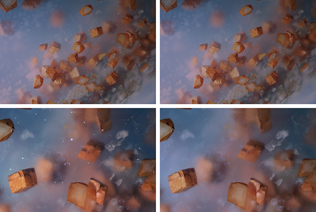
HDR is another useful processing technique. In digital photomicrography, reflections from facets and other inclusions can create scenarios where some areas of the image are beyond the dynamic range of the camera sensor. In other words, the difference between the lightest and darkest areas in the inclusion scene is beyond what the camera sensor can measure in a single image. The most effective approach is to effectively control the illumination source so that all lighting that falls in the image frame is within the camera’s ability to capture. Another consideration is adjusting the camera’s ISO setting to the lowest possible value. This typically allows the camera to operate at the largest possible dynamic range. HDR imaging can help combat the appearance of overly bright or dark areas in an image when lighting cannot be controlled to eliminate loss of detail. Similar to focus stacking, the photomicrographer must capture several images that are combined into one final image. Instead of changing the focus, as with image stacking, the exposure time is changed. Details resolvable at several different exposures are combined into a single image that is beyond the detail possible from any single exposure. Sometimes this effectively reproduces what the gemologist actually sees when observing the specimen in the microscope. The human brain and eye do not suffer from the relatively narrow dynamic range of a digital camera sensor, so in some cases, a high dynamic range image may approximate the actual subject than any single exposure alone (figure 20). HDR imaging can be accomplished using software designed for this task, often available on the Internet, such as Nikon NIS Elements, Canon Digital Professional, Oloneo HDR, and Photomatix Pro. Some cameras have built-in HDR processing capabilities, including many smartphones and some Canon and Nikon DSLR cameras. This convenient built-in feature helps automate HDR imaging without the need for secondary image-processing software.

Other types of post-processing digital image software help the photographer make fine adjustments to the captured image. Sometimes the settings used to capture an image can be improved. Unlike film-based photography, the digital world offers tools to modify brightness, contrast, and color without having to retake a photograph or take several exposures at different settings to see which one looks best. Some digital software also offers enhancement tools that clean up images and remove artifacts such as minute spots of dust on the sample or spot artifacts from dust on the camera sensor (figure 21). These tools help photographers adjust images to more accurately represent their subjects. The most popular of these programs is almost certainly Adobe Photoshop, but many photography-specific post-processing programs have been developed with the onset of digital photography. Photoshop Lightroom is also a popular option for image post processing and organization, but other programs such as Pixelmator (for Macs and iPads) and GIMP (GNU Image Manipulating Program) offer easy-to-use digital image correction tools. Photomicrographers will also want to consider the file type. Raw files are much larger than JPEG files, but also better for post-image processing adjustments.
SUBJECT SIZE
One of the most important attributes conveyed by a photomicrograph is the size of the subject. There are a few ways to present this information: indicating the magnification used to capture the image for a particular format (size of the camera sensor), overlaying a scale bar onto the image itself, or indicating the field of view as a numerical measurement. Gemological texts have historically indicated the magnification that was used to observe a subject to convey the relative size of the inclusion scene and how it would look in the reader’s own microscope. The rationale here is that most gemologists are familiar with the magnification range used during routine gemological microscopy, which may not be true of a numerical value presented in a possibly unfamiliar unit, such as microns. The biggest problem with using magnification in the digital age is maintaining accuracy during the post-processing phase, as images are often formatted and cropped in ways that render the original magnification meaningless.
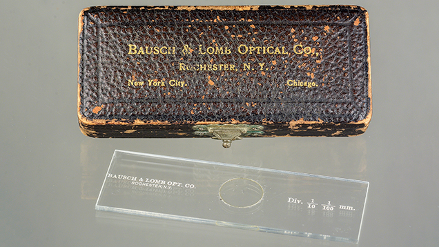
The magnification factor of an optical microscope is determined by multiplying the magnification factors of all optical components between the specimen and the observer’s eye. While this represents the observed magnification, the actual magnification of the recorded image can vary depending on the size of the camera sensor, and will likely be very different from the observed magnification factor. The easiest method to determine the magnification at the camera sensor is to use a microscope calibration slide (figure 22) to determine the actual field of view the camera captures. If the field of view and the physical size of the camera sensor are known, then the magnification factor at the camera sensor can be calculated by dividing the sensor width by the horizontal field of view of the subject as measured by the calibration slide. This recorded magnification becomes meaningless as soon as the image is cropped or enlarged from the original footprint of the camera sensor, which will almost certainly occur. This is why a more precise way to communicate the actual size the photomicrograph represents is needed. This can be accomplished by the use of a scale bar or a field of view measurement.
In most scientific publications, scale bars are used to indicate subject size by overlaying a line of known length on some portion of the photomicrograph (Hord, 2004). This is an accurate way to convey subject size in a photomicrograph. Some software, such as Helicon Focus, provides a tool that lets the user quickly add a scale bar to their images. Despite the benefit of the information they contain, scale bars do obscure a portion of the image. Gemology is an observational science, and gemologists are privileged to view beautiful scenes that are preserved in photomicrographs. The artificial addition of a scale bar may be perceived as an unnecessary blemish on an otherwise artistic scene, which is reason enough for this author to exclude scale bars. Fortunately, there is a compromise that overcomes the problems with using magnification and scale bars to convey subject size: expressing a field of view measurement for the final image in the caption. This offers an accurate account of subject size without marring an otherwise pristine inclusion scene with an unsightly scale bar.
CONCLUSIONS
Photomicrography is a tremendously rewarding aspect of gemology. It appeals to all types of practitioners, from scientists to artists and everyone in between. With technological developments in the last decade, digital-format photography has spurred the development of a wide range of tools to enhance images in ways never before possible. Digital photography has also helped to offset cost-related issues, since there are almost no consumable items that the photomicrographer must purchase after an initial investment in equipment, allowing many more people to participate in this branch of gemology.
Because of the spectacular level that digital technology has already achieved in the last decade alone, it is hard to imagine how photomicrography might evolve in the next 10 years. One area with significant room for improvement is lighting options. Light-emitting diode technology is improving at a rapid rate, and the implementation of LED lighting in photomicrography will be a welcome improvement, as it comes closer to “natural-looking” full spectrum lighting. Camera technology will likely continue to improve as higher-resolution and higher-sensitivity sensors are developed. Canon recently announced the release of a full-frame DSLR with more than 50 megapixels of resolution, the highest of any 35mm format camera to date (Canon, 2015). Two models, the 5DS and 5DSR may prove to be well suited for photomicrography. Vibration may also be curtailed as mirrorless digital cameras become more refined. Hopefully, the overall cost of digital camera equipment will be lower, allowing more users to acquire better equipment and capture better images.
With practice and patience, anyone can enjoy this branch of gemology and share their observations and discoveries within the micro-world of gems.


